Leave Your Message
-
Phone
-
E-mail
-
Whatsapp
-
WeChat

When it comes to recycling oil sludge these days, it’s not just about how fast the separation happens anymore. Buyers are really looking at the whole picture — things like how well they can recover the oil, the quality of the water afterward, how much energy the equipment uses, how easy it is to do maintenance, and how straightforward it is to handle the leftover residue. In this article, we’ll introduce you to the Top 10 Oil Sludge Recycling Equipment makers who are shaping these decisions. We’re comparing various types of equipment — think centrifuges, thermal desorption units, screw presses, chemical conditioning systems, and fully integrated treatment lines — to help you get a better sense of what’s out there.
Remember what Dr. George Tchobanoglous, a well-respected environmental engineer, once said: “The main goal of solid waste management is to protect public health and the environment.” That idea definitely holds true when it comes to treating oil sludge. A machine might look great in a demo, but in real-world operations, it’s gotta do more. It should be able to handle sticky sludge, viscosity that keeps changing, sand-like particles, and unstable water content. Take the feed pump, for example — if it gets a blocked screen, it can shut down the entire process, and nobody wants that!
There are some big players in the game — Alfa Laval, ANDRITZ, GEA, Flottweg, Hiller Separation, GN Solids Control — each bringing their own technical twist to the table. Then you’ve got others like KMT International, Oilybits, Brightway, and even King Abdulaziz City for Science and Technology making waves. These manufacturers differ quite a bit when it comes to automation, throughput capacity, heating design, and after-sales support. Honestly, no single brand or model is perfect. Something that works like a charm in a refinery might not be suitable at a remote storage site. The best way to tell? Well, it really comes down to lab testing, checking references from the field, and looking at solid performance data.
And don’t just buy into vague claims about recovery rates. You need to pay attention to details like how much oil and moisture they’re actually able to recover, making sure residence times and operating temperatures match real-world conditions. Little things matter — like a poorly insulated pipe that quietly causes more fuel consumption.” This guide is all about focusing on practical, real-world evidence rather than just flashy brochures or marketing hype.
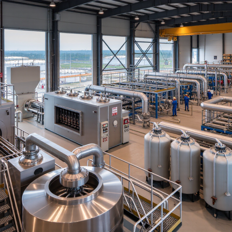
Oil sludge is not simply dirty water. It usually contains crude hydrocarbons, water, sand, clay, salts, corrosion products, and chemical residues. Storage tanks may hold thick black layers, while lighter fractions release volatile organic compounds. Benzene, polycyclic aromatic hydrocarbons, heavy metals, and hydrogen sulfide can threaten workers, soil, and groundwater.
Reported volumes remain difficult to compare. There is no consistent global inventory for oil sludge. IOGP environmental performance reports show that waste figures depend heavily on operator boundaries, regional rules, and reporting methods. A neat global total would be convenient, but probably misleading. UNEP’s Global Waste Management Outlook 2024 projects municipal waste rising from 2.3 billion tonnes in 2023 to 3.8 billion tonnes by 2050. Oil sludge is only one industrial stream, yet this trend highlights growing pressure on treatment capacity.
Practical recycling begins with sampling, heating, screening, centrifugation, and controlled oil recovery. Moisture and solids can change equipment performance within hours. Cooling also needs care. Oil Drilling Mud Cooling Equipment may help control temperature during drilling-fluid handling, but it does not replace sludge treatment. EPA waste guidance emphasizes characterization before selecting recovery or disposal routes. In the field, incomplete sampling remains a weakness. A single tank sample can miss settled metals and water pockets, creating false confidence in recovery rates. Reliable facilities therefore document feed composition, emissions, recovered oil, and residual solids for every batch.
The table below compares ten non-branded oil-sludge recycling equipment configurations. Technical ranges are typical industry values and vary according to feed composition, regulatory requirements, and plant design.
| No. | Equipment Configuration | Primary Separation Technology | Typical Feed Capacity (m³/h) |
Suitable Oil-Sludge Composition | Typical Water Content (wt%) |
Typical Oil Content (wt%) |
Main Recovered Products | Key Hazard-Control Function |
|---|---|---|---|---|---|---|---|---|
| 1 | Heated Oil-Water Separator | Gravity separation with controlled heating and skimming | 1–50 | Free oil, water, and settleable solids | 60–90 | 2–20 | Separated oil and treated water | Reduces free hydrocarbons and limits uncontrolled discharge |
| 2 | Dissolved Air Flotation Unit | Microbubble flotation after coagulation and flocculation | 5–100 | Fine oil droplets and suspended solids | 70–98 | 0.5–10 | Float sludge and clarified water | Removes dispersed oil and solids before polishing treatment |
| 3 | Three-Phase Decanter Centrifuge | Continuous centrifugal separation of oil, water, and solids | 1–40 | Pumpable sludge with mixed liquid phases | 40–85 | 5–30 | Recovered oil, centrate water, and dewatered solids | Enclosed operation reduces worker exposure to vapors and splashes |
| 4 | Disc-Stack Centrifuge | High-speed centrifugal clarification and liquid-liquid separation | 0.5–30 | Low-to-moderate solids and fine oil droplets | 60–95 | 1–15 | Polished oil phase and clarified water | Improves effluent quality by capturing small suspended particles |
| 5 | Screw Press Dewatering System | Low-speed mechanical pressing and gravity drainage | 0.5–15 | High-solids sludge after primary oil removal | 60–90 | 2–15 | Dewatered solids and filtrate | Reduces sludge volume, transport requirements, and free-liquid hazards |
| 6 | Filter Press System | Batch pressure filtration using recessed or membrane plates | 0.2–20 | Flocculated sludge with substantial suspended solids | 55–85 | 1–12 | Filter cake and filtrate | Produces a stackable cake that is easier to handle and contain |
| 7 | Thermal Desorption Unit | Indirect heating to volatilize hydrocarbons without direct combustion | 0.2–10 | Hydrocarbon-rich solids and difficult emulsions | 10–40 | 5–35 | Recovered hydrocarbon vapor and treated solids | Controls hydrocarbon contamination through condensation and off-gas treatment |
| 8 | Vacuum Evaporation and Condensation System | Low-pressure evaporation followed by vapor condensation | 0.1–15 | Water-rich sludge or wastewater concentrate | 70–98 | 0.1–8 | Condensed water and concentrated residue | Minimizes liquid waste volume and allows vapor capture in a closed system |
| 9 | Solvent Extraction and Recovery Line | Selective hydrocarbon extraction, phase separation, and solvent recovery | 0.2–8 | Aged sludge with strongly bound hydrocarbons | 20–70 | 10–40 | Recovered oil, recycled solvent, and treated solids | Requires explosion-proof design and strict solvent-vapor control |
| 10 | Integrated Pretreatment and Polishing Train | Screening, heating, chemical conditioning, centrifugation, and final filtration | 5–100 | Variable refinery, terminal, and tank-bottom sludge | 40–95 | 1–35 | Recovered oil, treated water, and stabilized solids | Combines containment, vapor management, dewatering, and discharge polishing |
| Data Dimension | Evidence-Based Range or Fact | Operational Significance |
|---|---|---|
| Water fraction | Commonly about 40–90 wt%, depending on source, storage conditions, and dewatering history | Determines pumping, heating demand, centrifuge loading, and final disposal volume |
| Hydrocarbon fraction | Often about 1–35 wt%; heavily weathered or tank-bottom sludge may fall outside this range | Influences recovery value, flammability controls, and treatment selection |
| Solid fraction | Typically includes mineral particles, corrosion products, scale, and organic solids; often about 5–40 wt% | Affects abrasion, cake formation, centrifuge torque, and residual-waste handling |
| Potential contaminants | May include volatile organic compounds, polycyclic aromatic hydrocarbons, sulfides, metals, salts, and chemical additives | Requires representative laboratory testing before recycling, reuse, or disposal |
| Main physical hazards | Fire, explosion, toxic vapor exposure, oxygen deficiency in confined spaces, and slippery surfaces | Calls for gas detection, ventilation, bonding and grounding, PPE, and confined-space procedures |
| Environmental hazards | Uncontrolled releases can contaminate soil and water and may harm aquatic organisms | Secondary containment and compliant wastewater, air-emission, and residual-solid controls are necessary |
| Global waste-volume availability | There is no universally accepted global inventory for oil sludge; published estimates differ because definitions and reporting boundaries vary | Use site-specific mass balances, tank-cleaning records, and regulatory manifests instead of one global figure |
| Recommended testing indicators | Water and oil content, total petroleum hydrocarbons, flash point, calorific value, pH, metals, sulfide, and PAHs | Supports equipment sizing, hazard classification, recovery planning, and final-treatment selection |
Note: Capacity and composition values are indicative engineering ranges, not guaranteed performance specifications. Actual results depend on viscosity, emulsion stability, particle-size distribution, temperature, chemical conditioning, and local environmental regulations.
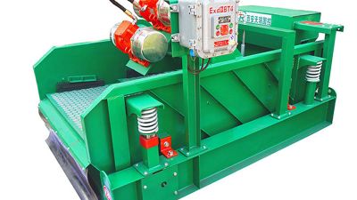
A linear shale shaker is a core piece of primary separation equipment in oil and gas drilling solids control systems. By applying linear motion, it efficiently removes drilled solids from drilling fluid, helping maintain fluid performance, protect downstream equipment, and support safer, more cost-effective drilling operations. Its stable screening action is suitable for continuous treatment of drilling fluids under demanding field conditions.
Designed for durability, this shaker screen is available in stainless steel 304, 316, or 316L. The PWP construction, featuring a perforated wear plate, provides strong support and improved resistance to abrasion. Its rectangular wear mesh shape promotes consistent solids separation, while API RP 13C designations from API 20 to API 325 allow operators to select an appropriate screening grade for different drilling requirements.
The screen can be configured for DX, DF, and HP series equipment and is finished in green for easy identification in the solids control area. As part of a third-generation linear motion shale shaker system, it contributes to high-efficiency solid-liquid separation and helps reduce fluid losses and operating expenses. Each carton contains two pieces, with the screens securely packed in a wooden case for transportation and site delivery.
Oil sludge contains hydrocarbons, water, sand, clay, salts, corrosion products, and chemical residues. A thick black layer may settle inside a storage tank.
It may contain volatile compounds, benzene, heavy metals, and hydrogen sulfide. These substances can harm workers, soil, and groundwater without proper controls.
No consistent global inventory covers every facility and region. Reported totals vary with operator boundaries, local rules, and reporting methods. A precise global number may create false confidence.
Facilities may use sampling, heating, mixing, screening, centrifugation, and controlled oil recovery. Moisture and solids can change equipment performance within hours. Preparation matters greatly.
One tank sample may miss settled metals, thick solids, or hidden water pockets. That can exaggerate recovery results. Better facilities test multiple locations and document each batch.
Some systems target 80–95% oil recovery and more than 90% solids reduction. Actual results depend on moisture, viscosity, solids, and contaminant levels. High recovery is possible, not automatic.
They should test recovered oil in a laboratory, rather than relying on appearance. They should weigh residual solids before and after treatment. Small measurement errors matter.
Sticky sludge may coat heated surfaces and lower throughput. Sand can wear pumps, conveyors, and separation components. Daily conditions are rarely as clean as demonstrations.
No. Cooling equipment can help control temperature during drilling-fluid handling. It does not remove oil, solids, or hazardous contaminants from sludge. The distinction is easy to miss.
Oil sludge recycling addresses a complex waste stream made up of oil, water, sediment, metals, and other contaminants generated during petroleum storage, transportation, and processing. Without proper treatment, this material can create soil and water pollution risks, operational problems, and significant disposal costs. Modern Oil Sludge Recycling Equipment uses staged separation, heating, centrifugation, filtration, and, where appropriate, thermal treatment to recover usable oil, reduce solids, and produce more manageable residuals. Well-designed systems may achieve approximately 80–95% oil recovery and more than 90% solids reduction, depending on sludge composition and operating conditions.
This overview compares leading equipment categories by technology, processing capacity, energy demand, emissions control, and regulatory suitability. Decanter centrifuges are valued for continuous mechanical separation, while thermal desorption offers stronger treatment for contaminated solids. Pyrolysis systems can convert certain organic residues into useful by-products but require careful temperature control and gas management. Selecting the right solution depends on throughput, moisture content, recovery targets, maintenance needs, environmental safeguards, and site-specific compliance requirements.