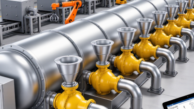
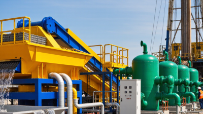
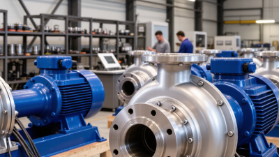
Ever wondered why a Drilling Desilter might be the right choice for your mud cleaning needs? Well, it’s mainly because a desilter is great at getting rid of those tiny sand and silt particles that can stick around even after your shale shakers and desanders have done their job. If you don’t keep these bits under control, they can bump up the mud density, wear down your equipment faster, and even slow down your drilling progress. Sometimes, it’s the little things—like cloudy discharge, unstable mud properties, or a cone packed with solids—that give you clues something’s off.
Dr. Johannes Fink, a respected expert in drilling fluids and petroleum engineering, once said, ‘Effective solids control depends on removing unwanted particles before they do any damage to the drilling system.’ That really hits the mark because it explains why choosing the right drilling desilter is so important. These units use centrifugal force with their hydrocyclones to separate out those lighter, unwanted particles. But don’t forget, performance doesn’t just depend on the machine itself; factors like feed pressure, cone size, mud properties, and regular maintenance play a big role too. Technology alone doesn’t do all the work.
From what folks in the field have seen, picking the right equipment isn’t just about the specs—it’s about being honest and realistic about what your mud actually requires. A desilter isn’t a magic fix for every mud problem, and it’s not meant to replace good practices like thorough mud testing or disciplined solids control procedures. That’s an important point to keep in mind. Before you pick a unit, it’s smart to check things like particle size distribution, flow rate, and how heavily you expect to load cuttings. Big companies like Derrick Equipment and NOV have shown that integrated solids-control systems really make a difference, but at the end of the day, how well your equipment performs depends heavily on your operating conditions.
A well-maintained Drilling Desilter can help keep your mud cleaner, ensure more consistent properties, and even extend the life of your equipment. At first, these improvements might seem pretty subtle. But over the course of a long drilling project, those small gains can add up to real savings and fewer unnecessary hiccups along the way.
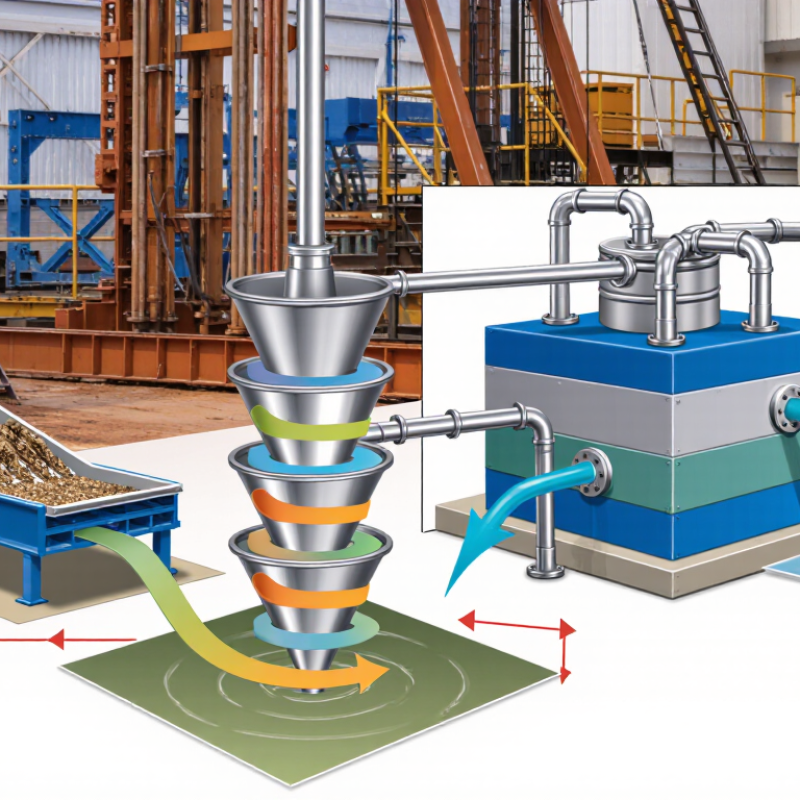
A drilling desilter is a solids-control unit that removes fine drilled particles from circulating drilling fluid. It commonly uses hydrocyclones, which separate solids through centrifugal force. The fluid enters each cone under pressure. Heavier particles move outward and leave through the lower opening. Cleaner fluid rises and returns to the active mud system.
A Drilling Fluid Desilter usually handles particles smaller than standard shale shakers can remove. Its working range often includes silt-sized solids, roughly 15 to 74 microns, depending on cone design and operating conditions. In the field, operators check feed pressure, fluid density, and discharge texture. A steady, thin underflow can indicate useful separation. A thick discharge may signal excessive fluid loss or poor adjustment.
The unit should match the mud system, pump capacity, and drilling conditions. Too little pressure reduces separation efficiency. Too much pressure can increase wear and waste valuable fluid. I have found that clean screens do not guarantee clean mud; cone performance still matters. It is not a magic filter. Changes in viscosity, solids loading, and temperature can alter results within hours. Regular inspection of cone tips, valves, and collection lines helps prevent unnoticed bypass. Sometimes, the most useful improvement comes from correcting upstream mixing or shaker performance.
A drilling desilter improves mud cleaning by removing fine drilled solids before they damage the fluid system. Its core component is a group of hydrocyclones. A pump sends drilling fluid into each cone under controlled pressure. The tangential entry creates a strong spiral flow inside the chamber.
Centrifugal force pushes denser solids toward the cone wall. The solids then travel downward and leave through the apex as underflow. Cleaner liquid moves upward through the vortex finder and returns as overflow. This separation can target particles commonly missed by screens, often within the 15–74 micron range, depending on cone design and operating conditions. Small changes matter. Feed pressure, mud viscosity, cone wear, and solids loading can change the result.
On a drilling site, I would check the discharge pattern before trusting the numbers. A steady, thin underflow often indicates useful separation. A dry rope may signal excessive pressure or a restricted apex. A flooded discharge can mean poor separation. It happens.
An Api Drilling Fluid Desilter should match the mud properties and expected flow rate, not only the advertised capacity. Operators should sample inlet and outlet mud regularly. Microscopic inspection can reveal whether valuable liquid is being discarded with the solids. The process is efficient, but never automatic. Poor maintenance or incorrect settings can return fine solids to the active system.
A Mud Desilter is more than a row of small cones. Its system normally includes a feed tank, centrifugal pump, suction line, pressure gauge, manifold, hydrocyclones, discharge chutes, and a cleaned-mud return line. The pump sends weighted drilling fluid through the manifold at controlled pressure. Each hydrocyclone creates a strong vortex. Heavier particles move outward and exit through the apex. Cleaner mud rises through the overflow outlet.
Small details matter. A blocked suction screen can starve the pump. Excessive pressure may increase wear without improving separation. Industry references, including the IADC Drilling Manual, commonly place desilter separation around 15–45 microns, depending on cone design and operating conditions. API RP 13C and ISO 13501 also promote standardized performance reporting, including separation behavior and cut-point evaluation. These references help engineers compare equipment using measured data, not attractive claims.
The underflow deserves attention. It should discharge solids freely into a waste container, while the overflow returns smoothly to the active mud system. Operators should check cone pressure, flow stability, mud density, and the condition of the apex during every shift. A clear sight glass helps. So does a clean pressure gauge. Field results can still disagree with laboratory data because viscosity, solids loading, and temperature change constantly. That limitation is easy to overlook. A well-designed system therefore needs accessible valves, safe maintenance space, and records from actual drilling intervals. Otherwise, even correctly sized hydrocyclones may deliver disappointing mud cleaning.
Why Choose a Drilling Desilter for Better Mud Cleaning?
How Does Desilter Cleaning Improve Drilling Mud Quality?
A drilling desilter removes fine sand, silt, and drilled solids from circulating mud. These particles can quietly increase mud density and viscosity. Small particles matter. In field checks, cleaner mud usually shows steadier rheology and more predictable filtration behavior. Hydrocyclones inside the desilter separate solids through centrifugal force. The process depends on feed pressure, cone condition, and mud properties. A poorly adjusted unit may waste liquid or return solids to the system.
Cleaner mud also supports better hydraulic performance. It reduces abrasive wear on pumps, valves, and downstream equipment. Lower fine-solid content can improve cuttings transport and help maintain planned mud density. This matters when the formation changes quickly. A mud engineer can compare inlet and outlet samples, check sand content, and monitor funnel viscosity. These simple checks make the improvement measurable.
The equipment is not a cure-all. Not always. Very sticky solids may require different treatment, while excessive dilution can hide an operating problem. I have seen operators focus on flow rate and overlook cone spray patterns. That mistake can reduce separation efficiency. Regularly inspect the manifold, confirm operating pressure, and remove blocked cones promptly. Mud quality improves when the desilter works as part of a controlled solids-management plan, not as an isolated machine.
How does desilter cleaning improve drilling mud quality?
A drilling desilter typically targets fine solids in the 15–44 μm range, which are often too small for conventional shale shakers and too large for efficient removal by some downstream equipment. Removing these low-gravity solids can help control plastic viscosity, reduce excessive filter-cake buildup, improve filtration behavior, and maintain more consistent drilling-fluid performance. Actual separation cut points vary with cone design, flow rate, operating pressure, mud density, and rheology.
Typical engineering separation ranges shown in micrometres (μm); they are not brand-specific performance guarantees.
Performance begins at the inlet, not the cone. An Oilfield Mud Desilter needs stable feed pressure, consistent flow, and sufficient residence time. API RP 13C stresses standardized equipment testing. IADC field guidance connects rheology, density, and solids control. Field audits commonly record desilter pressure near 60–75 psi. The correct value still depends on cone geometry and mud properties. Too little pressure reduces separation. Too much pressure increases wear and bypass risks.
Small details matter.
Mud viscosity strongly affects performance. A heavy, gelled system can carry particles through the cyclone. Temperature changes may alter viscosity during a night tour. Particle size distribution matters as well. Many desilters target approximately 15–45 micrometres, although cut points shift with pressure, density, and cone condition. SPE technical case studies often report lower efficiency when screens, manifolds, or cones become partially plugged. The gauge may look normal. The discharge may disagree.
Inspect the underflow pattern every shift. A thin, steady spray usually indicates useful separation. A rope-like discharge may signal plugging or excessive solids loading. Compare inlet and outlet sand content through calibrated testing, not eyesight alone. IADC training materials recommend routine sampling and trend records. One assumption deserves reconsideration: higher pressure does not automatically mean cleaner mud. Record pressure, flow, temperature, funnel viscosity, and cone wear together. Adjust one variable at a time. That takes patience.
| Performance Dimension | Typical Operating Data | Effect on Mud Cleaning | Recommended Control Point | How to Verify Performance |
|---|---|---|---|---|
| Particle Separation Range | Hydrocyclone desilters commonly target solids in the approximately 15–75 µm range, depending on cone design, mud properties, and operating pressure. | Removes a significant portion of fine sand and silt that can increase viscosity, abrasion, and poor filter-cake quality. | Select a desilter after defining the desired cut size and the solids-control requirements of the drilling fluid system. | Compare particle-size distribution in the desilter feed and cleaned-mud stream. |
| Feed Pressure | Many systems operate in the approximate range of 20–40 psi (1.4–2.8 bar), subject to cone specifications and process design. | Insufficient pressure reduces centrifugal force and separation efficiency; excessive pressure can increase wear and energy consumption. | Maintain stable pressure within the cone manufacturer’s operating window rather than maximizing pressure. | Install a calibrated pressure gauge upstream of the hydrocyclone manifold and record pressure during operation. |
| Feed Flow Rate | Flow capacity depends on cone diameter and configuration; a typical 4-inch cone may process roughly 50–80 gpm (190–300 L/min) under suitable conditions. | Low flow can cause weak separation, while overloading may carry coarse solids into the cleaned-mud stream. | Match the number of active cones to the actual circulating flow and keep loading reasonably balanced. | Monitor pump rate, manifold flow, pressure stability, and the number of cones in service. |
| Mud Density | Common drilling-fluid densities may range from about 8.6 to 18.0 ppg (1.03–2.16 SG), depending on the well program. | Higher density changes the pressure-flow relationship and can reduce separation performance if the unit is not properly sized or adjusted. | Evaluate desilter capacity and pressure using the actual mud density, not water-based test data alone. | Measure inlet and outlet density with a calibrated mud balance and track changes over time. |
| Plastic Viscosity | Operational values vary widely; approximately 10–40 cP is common for many water-based drilling fluids. | Higher viscosity increases flow resistance and may reduce the hydrocyclone’s ability to separate fine solids. | Use dilution, solids removal, or rheology treatment when viscosity rises beyond the drilling-fluid program limit. | Check plastic viscosity and yield point at consistent temperature and testing conditions. |
| Solids Loading | Performance is affected by the concentration, size distribution, and mineral type of drilled solids entering the unit. | High solids loading can overload cones, increase underflow losses, and reduce the quality of the cleaned mud. | Use primary shale-shaker and desander treatment upstream where appropriate to reduce the desilter’s solids burden. | Track low-gravity solids, retort results, sand content, and the mass or volume of discharged solids. |
| Cone Condition | Cone liners, inlets, apexes, and vortex finders are wear components; erosion changes their internal geometry. | Worn or damaged parts can increase bypass, alter the cut point, destabilize the underflow, and reduce separation consistency. | Inspect components routinely and replace parts when wear affects the specified operating profile. | Check for enlarged apex openings, cracks, abnormal spray patterns, and changes in pressure or underflow behavior. |
| Underflow Pattern | A stable spray or controlled discharge generally indicates that the cone is receiving suitable pressure and flow. | A roping discharge may indicate overloading, an undersized apex, high viscosity, or inadequate operating conditions. | Adjust flow, pressure, cone count, or apex configuration to maintain a stable discharge pattern. | Inspect the underflow visually and record discharge condition for each active cone. |
| Apex Size and Configuration | Apex selection is application-specific; smaller openings generally increase concentration, while larger openings reduce plugging risk and may increase liquid discharge. | Incorrect sizing can cause roping, excessive mud loss, plugging, or insufficient solids removal. | Select the apex according to mud rheology, solids loading, pressure, and acceptable liquid loss. | Measure discharge consistency and compare liquid loss with the recovered-solids concentration. |
| Temperature | Drilling-fluid temperature may vary substantially with well depth, circulation time, and surface conditions. | Temperature changes can alter viscosity and therefore affect pressure, flow, and separation behavior. | Evaluate mud properties at representative operating temperature when assessing desilter performance. | Record temperature together with rheology, density, and desilter pressure readings. |
| Mud Loss and Recovery | Liquid loss varies with apex size, mud type, solids concentration, and underflow operating condition. | Excessive liquid discharge raises fluid-treatment costs, while insufficient discharge may allow undesirable solids to remain in the active system. | Balance solids removal efficiency with acceptable liquid loss and use recovery equipment when economically justified. | Measure discharge volume, solids concentration, and the density or properties of recovered fluid. |
Note: Operating ranges are representative field guidance only. Actual performance depends on hydrocyclone geometry, drilling-fluid formulation, solids characteristics, pump condition, and the complete solids-control layout.
Selecting a drilling desilter requires more than matching a catalog flow rate. Start with the mud system, expected solids loading, and target particle size. A unit should handle the active mud volume without excessive pressure loss. Cone diameter and quantity also affect separation efficiency. Smaller cones remove finer solids, but they usually demand stable feed pressure.
Check the mud properties before choosing equipment. High-viscosity fluid may require dilution or improved upstream screening. Abrasive formations can accelerate wear around the inlet and cone outlets. Measure twice. Small errors matter.
In field operations, technicians should compare actual flow with the manufacturer’s operating range. A simple pressure gauge and daily solids record can reveal poor performance earlier than visual inspection.
Maintenance should follow the drilling schedule, not only equipment failure. Inspect cones, liners, screens, seals, and feed lines for cracks or unusual wear. Flush settled solids before they harden inside the manifold. Keep spare wear parts dry and clearly labeled. Clean the unit with suitable water pressure, avoiding damage to screens and seals. Operators should also record pressure, vibration, discharge condition, and replacement dates. No selection chart is perfect. Formation changes, temperature, and recycled mud can alter performance. If the underflow becomes unusually wet or the overflow carries visible grit, stop and investigate the feed balance, blockage, or worn components. An experienced crew leaves room for correction.
A drilling desilter removes fine drilled particles from circulating drilling fluid. It commonly uses hydrocyclones and centrifugal force. Cleaner fluid returns to the active mud system.
Many units target silt-sized particles between about 15 and 74 microns. Actual separation changes with cone design, pressure, density, and viscosity. The cut point is not fixed.
Pressurized fluid enters the cone and spins rapidly. Heavier particles move outward and exit through the lower opening. Cleaner fluid rises through the upper outlet.
Field operation often uses about 60–75 psi. The correct pressure depends on cone geometry and mud properties. Too little pressure reduces separation. Too much increases wear and fluid loss.
A thin, steady spray often indicates useful separation. A rope-like or very thick discharge may signal plugging or heavy solids loading. Wet discharge can also mean excessive fluid loss.
Viscosity, density, temperature, and solids concentration strongly affect separation. Thick, gelled mud may carry particles through the cone. Nighttime cooling can change viscosity within hours.
Check pressure, flow, temperature, viscosity, discharge texture, and cone condition each shift. Compare inlet and outlet solids using calibrated tests. Eyes alone can mislead.
Inspect cones, liners, screens, seals, valves, and feed lines for wear or cracks. Flush settled solids before they harden. Keep replacement parts dry and clearly labeled.
The unit may lose excessive fluid, bypass fine solids, or suffer rapid wear. Match cone size and quantity with flow, mud volume, and expected solids loading. Catalog flow rates are not enough.
No. Upstream mixing or shaker problems may cause poor results. Clean screens do not guarantee clean mud. Sometimes, correcting the feed system helps more than increasing pressure.
A Drilling Desilter is a specialized solids-control device used to remove fine sand, silt, and other unwanted particles from drilling mud. By using hydrocyclones and controlled centrifugal force, it separates smaller solids that may remain after shale shaker and desander treatment. A typical system includes hydrocyclone cones, a feed pump, a manifold, an underflow collection area, and a supporting frame or tank. Together, these components help maintain stable mud circulation and improve separation efficiency.
Effective desilter cleaning can reduce excessive fine solids, protect drilling equipment, improve fluid properties, and support smoother wellbore operations. Performance depends on factors such as mud flow rate, pressure, viscosity, solids concentration, cone condition, and correct operating settings. Selecting a suitable Drilling Desilter requires matching its capacity and separation range to the drilling system. Regular inspection, cleaning, wear monitoring, and timely replacement of damaged parts are also essential for reliable performance and longer service life.